.pdf
.pdf
Heat Transfer in a BWM Motor
This case study is provided gracefully by SZE University in Györ (Hungary). Many thanks to Zoltan Horvath, Lotfi Abdelhakim.
1. Running the case
The command line to run this case is
mpirun -np 30 feelpp_toolbox_heat --case "github:{repo:toolbox,path:examples/modules/heat/examples/motor}"2. Data files
The case data files are available in Github here
3. Main Objectives
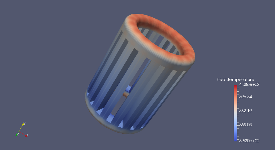
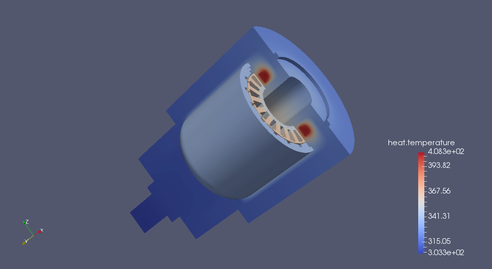
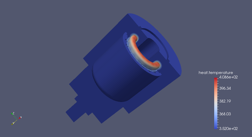
The main objective of this case is to develop a thermal model for finding the temperature distribution of different components of an electric motor during its various operating conditions and to determine the heat removal by natural convection from the machine surface.
The application allows the predictions of simultaneous heat transfer in solid and fluid media with energy exchange between them. The prediction of the temperature distribution inside an operating electric motor is required at the machine design stage. Excessive temperature in the motor can cause electrical insulation failure, demagnetization of the magnets and increase in Joule losses.
4. Geometry
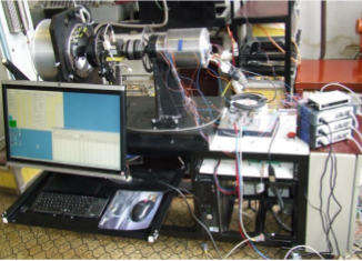
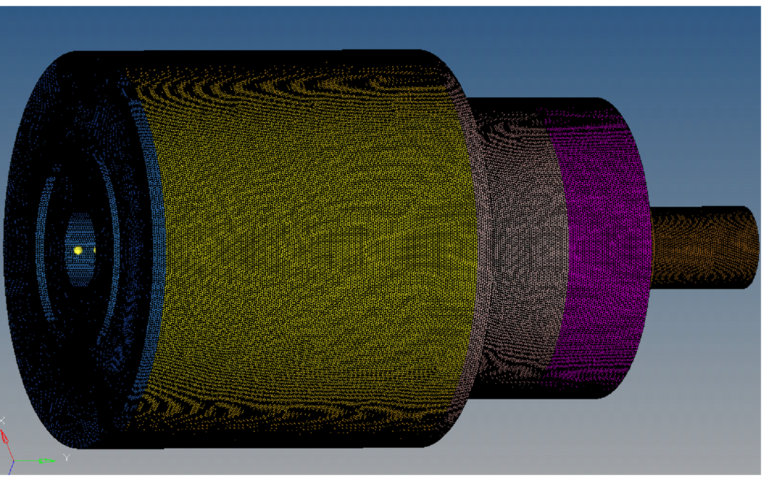
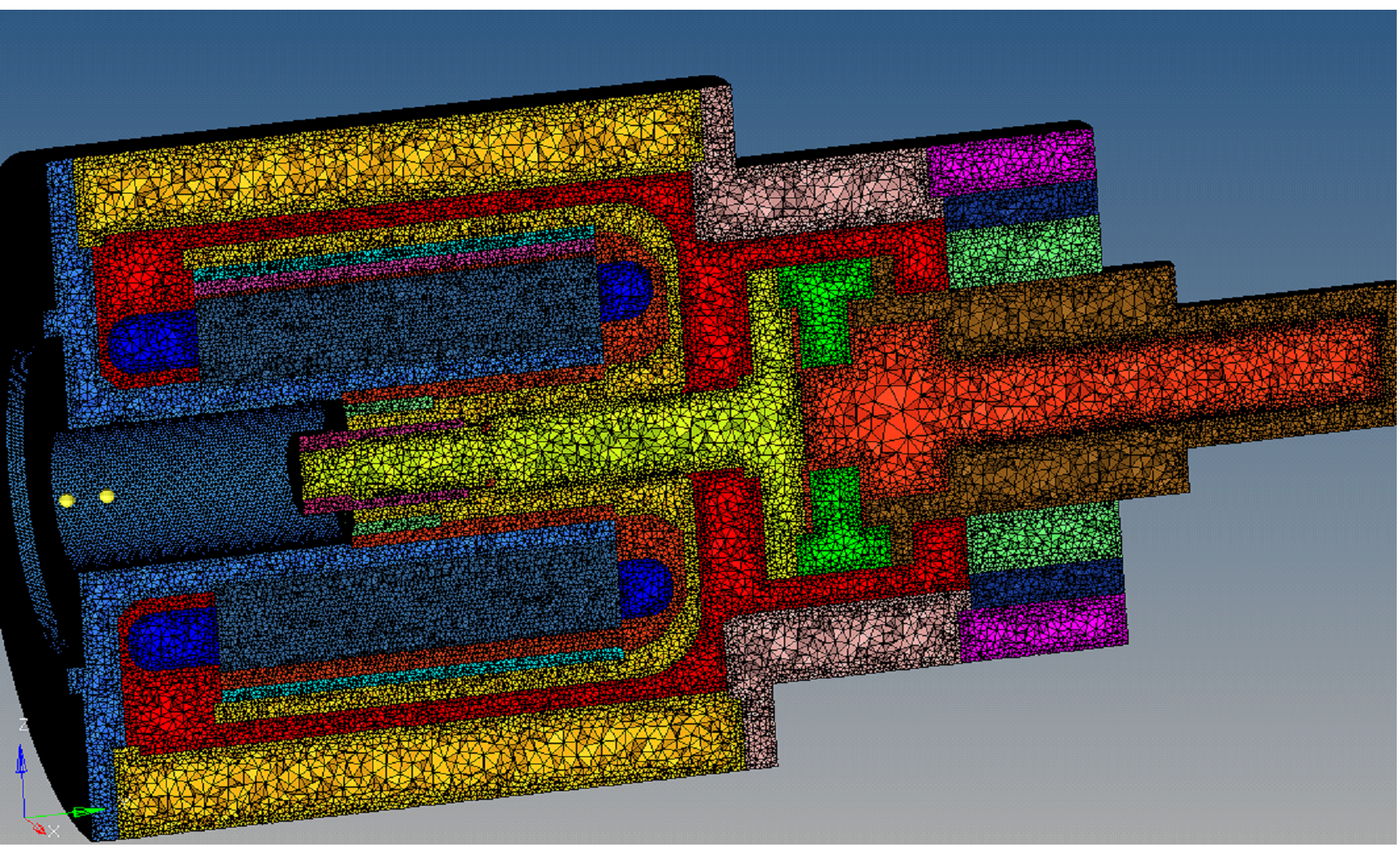
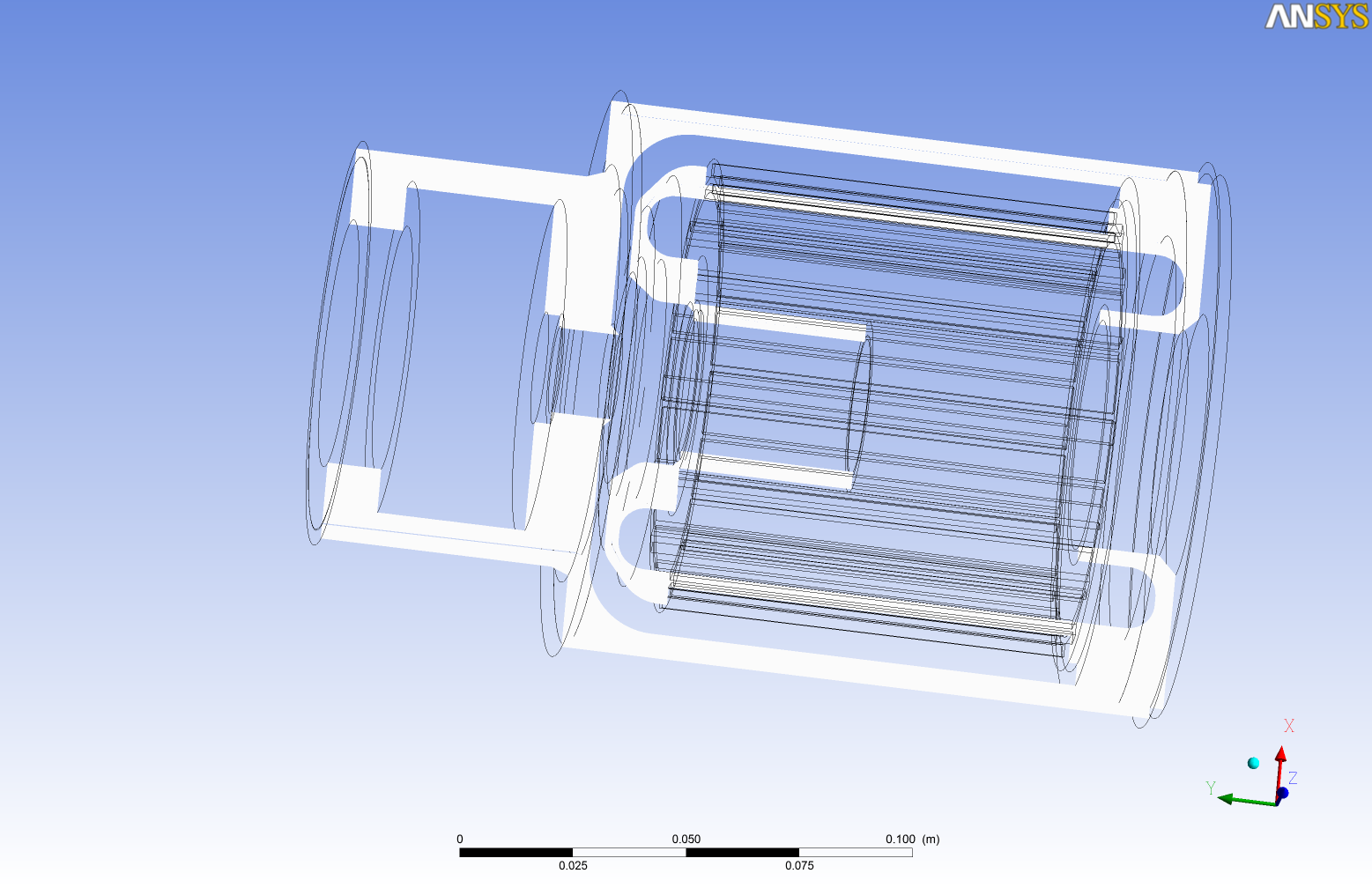
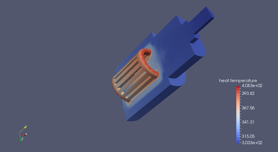
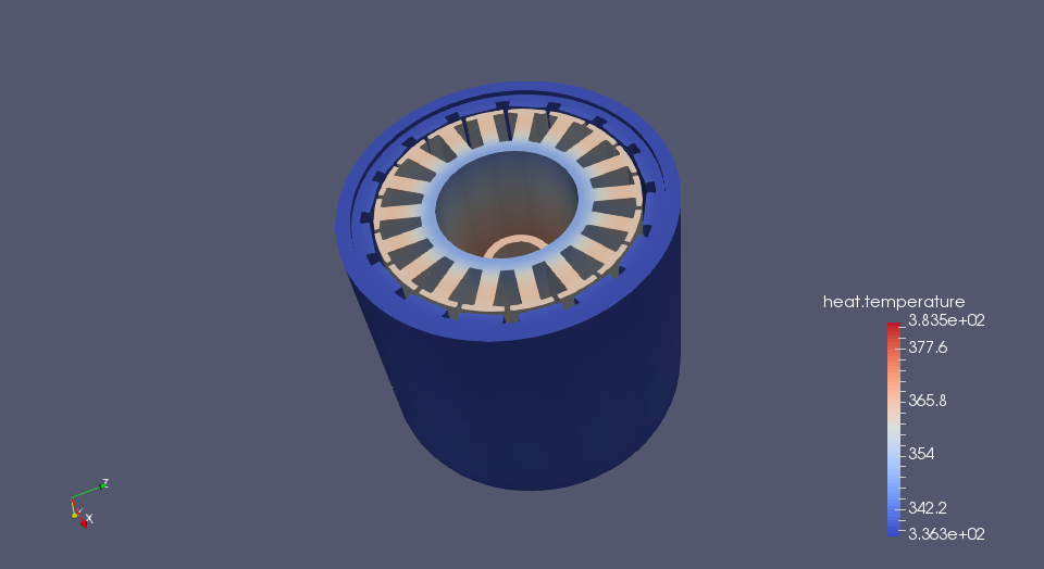
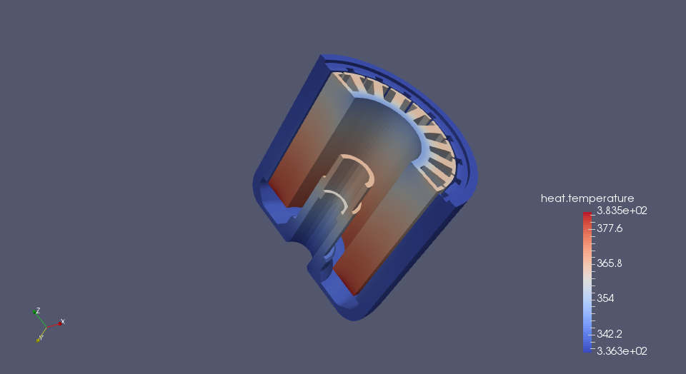
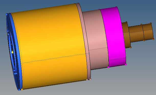
As shown in Fig. 1, the electric motor model has a very complicated geometry. Obviously, it is not possible to perform simulation on the entire PM motor, due to the large number of volumes and calculations required. Therefore, a part of the PM motor consisting of each part (front cover, stator core, stator windings, rotor, permanent magnets, shaft, external housing and the air-gap between these components are modelled for this study as shown on the Fig. 2. Fig. 3. shows a detailed view of the main components of the modeled electric motor.
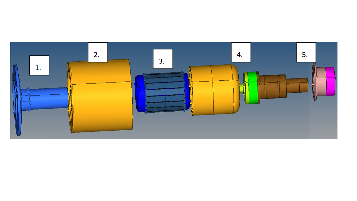
Model detail includes; (1) the front cover, (2) and (5) the external housing geometry, (3) the stator core geometry including slot detail and the stator windings, (4) the rotor geometry including permanent magnets and shaft. In order to simplify the model, the winding region was modeled as a solid section and the end winding region was modeled as a torus. This assumption made this motor element easier to mesh.
As shown in Fig. 4, the mesh for the motor and the air-gap was created based on tetrahedral elements, as these are the only elements capable of meshing that domain.