 .pdf
.pdf
Oscillating cylinder
Analysis Type: Numerical grid deformation Benchmark
| this benchmark has been published by NAFEMS, it has not yet been implemented/tested using Feel++ |
1. Introduction
CFD simulations often require moving boundaries either to model the prescribed motion of the structural elements (e.g. closure of a valve) or the direct response of the body to the fluid motion (e.g. a cylinder in cross-flow). When the so-called body fitted numerical meshes and underlying models are used, the numerical grid has to follow such boundary motion. This requires the numerical grid to deform without losing the ability to discretize the fluid flow equations and to reach a converging solution.
The quality of the numerical grid is often judged by the size and distribution of the control volume angles. If any element angle becomes too small or even negative, the numerical simulation will fail. Although the numerical grid deformation may decrease the minimum size of the control volume angle, any periodic deformations shall not lead to its permanent reduction.
2. Objectives
Test the grid deformation capability by examining the extent of permanent element deformation due to periodic boundary displacements. Minimal face angle of all control volumes in the simulation domain can be used to characterize performance of the grid deformation algorithm.
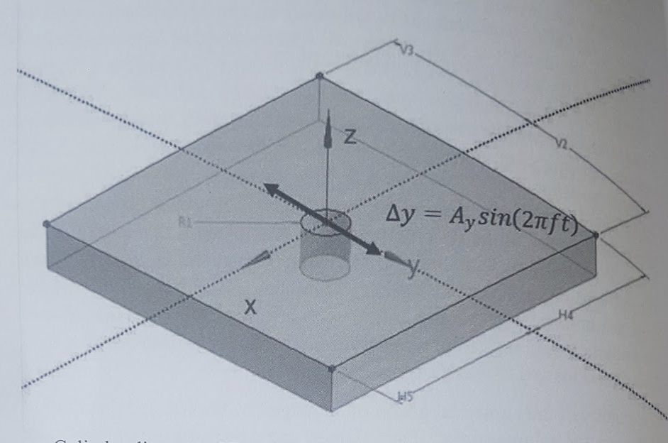
3. Geometry
-
Cylinder diameter \(\left(2 \mathrm{R}_{1}\right)\) is \(0.2 \mathrm{m}\)
-
Domain length \((\mathrm{H} 4+\mathrm{H} 5)\) and width \((\mathrm{V} 2+\mathrm{V} 3)\) are \(1.6 \mathrm{m}\)
-
Domain height is \(0.2 \mathrm{m}\).
4. Case Definition
Sinusoidal oscillations in the y-direction are forced by prescribing a displacement function \(\Delta y=A_{y} \sin (2 \pi f t)\) to the cylinder where:
-
\(A_{y}\) is the displacement amplitude set to \(0.2 \mathrm{m}\)
-
\(\cdot f\) is the forced oscillation frequency set to \(20 \mathrm{Hz}\) (the oscillation frequency does not influence the grid deformation although it determines the size of the integration timestep):
-
\(t\) is time.
5. Fluid Properties
Not applicable; the test scenario is limited to the grid deformation capability of the simulation algorithm.
7. Boundary Conditions
-
Zero displacement \((\Delta x=0, \Delta y=0)\) for the external domain boundaries at \(\mathrm{x}_{\min }, \mathrm{x}_{\max }, \mathrm{y}_{\min }\) and \(\mathrm{y}_{\max }\)
-
Prescribed grid displacement \(\left(\Delta x=0, \Delta y=A_{y} \sin (2 \pi f t)\right)\) for the cylinder walls; Symmetry or equivalent conditions for any motion in the z-direction.
8. Output
Investigate the minimum face angle using:
-
Diagram of the minimum face angle as a function of the simulated time
-
Diagram of the minimum face angle as a function of the displacement;
-
Minimum face angle change per period. In general, the smaller the change of the minimum angle, the better the gi deformation algorithm.