Spring
2. Running the case
The command line to run this case is
mpirun -np 4 feelpp_toolbox_solid --case "github:{repo:toolbox,path:examples/modules/csm/examples/spring}"3. Data files
The case data files are available in Github here:
4. Geometry
The geometry consists of a 7-turn coil spring. The spring is 4.5cm long and its radius is 1cm. The wire’s radius is 1mm.

The mesh is available on Girder
5. Input parameters
5.1. Model & Toolbox
The model used is the linear elasticity described in the CSM toolbox, see Computational Solid Dynamics
5.2. Materials
The coil spring is entirely made of steel.
| Name | Description | Value | Unit | |
|---|---|---|---|---|
\(E_s\) |
Young’s modulus |
\(210 \times 10^6\) |
\(kg.m^{-1}.s^{-2}\) |
|
\(\nu_s\) |
Poisson’s ration |
\(0.33\) |
\(dimensionless\) |
|
\(\rho_s\) |
density |
\(7850\) |
\(kg/m^3\) |
"Materials":
{
  "lumenVolume":
  {
    //#acier : http://www.simulationmateriaux.com/ComportementMecanique/comportement_mecanique_Liste_modules_de_Young.php
    "name":"steel",
    "E":"210e6", // [kg.m^{-1}.s^{-2}] (Young's modulus)
    "nu":"0.33", // dimensionless
    "rho":"7850" // [kg/m^3]
  }
},
We also need gravity:
"Parameters":
{
  "dispImposed":
  {
    "value":"8e-3" // [m]
  },
  "gravity":
  {
    "value":"9.80665" // [m.s^{-2}]
  }
},
5.3. Boundary conditions
The top and bottom ends of the spring are were the boundary conditions are applied. More precisely, we apply boundary conditions on the corresponding surfaces. We also apply gravity as a volumic force on the whole domain.
5.3.1. Top end
We apply a Dirichlet boundary condition here: the spring is considered attached to a fixed body on this surface. This means the displacement is zero on this surface.
5.3.2. Bottom end
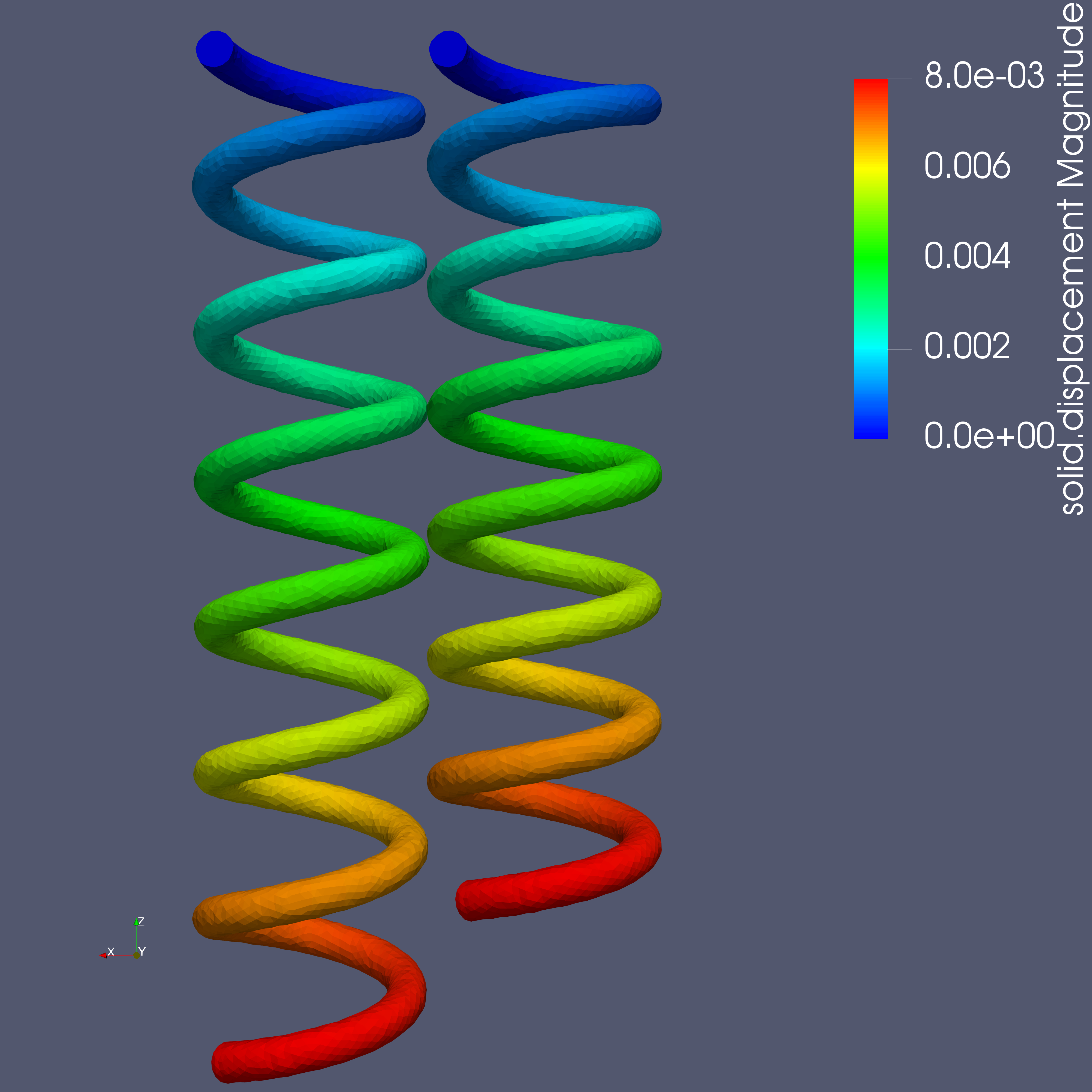
On this end, we also impose the displacement, but this time it is non-zero. This model the application of a certain pulling force along the spring axis which stretches it by 8mm.
5.3.3. Volumic force
Gravity is applied as a volumic force on all the elements of the mesh.
"BoundaryConditions":
{
  "displacement":
  {
    "Dirichlet":
    {
      "markerBottom":{ "expr":"{0,0,-dispImposed}:dispImposed" }, // imposed displacement -> pulled down end of the spring
      "markerTop":{ "expr":"{0,0,0}" } // imposed displacement (zero) -> fixed end of the spring
    },
    "VolumicForces":
    {
      "lumenVolume":
      {
        "expr":"{0,0,-gravity*7850}:gravity"
      }
    }
  }
},
6. Results
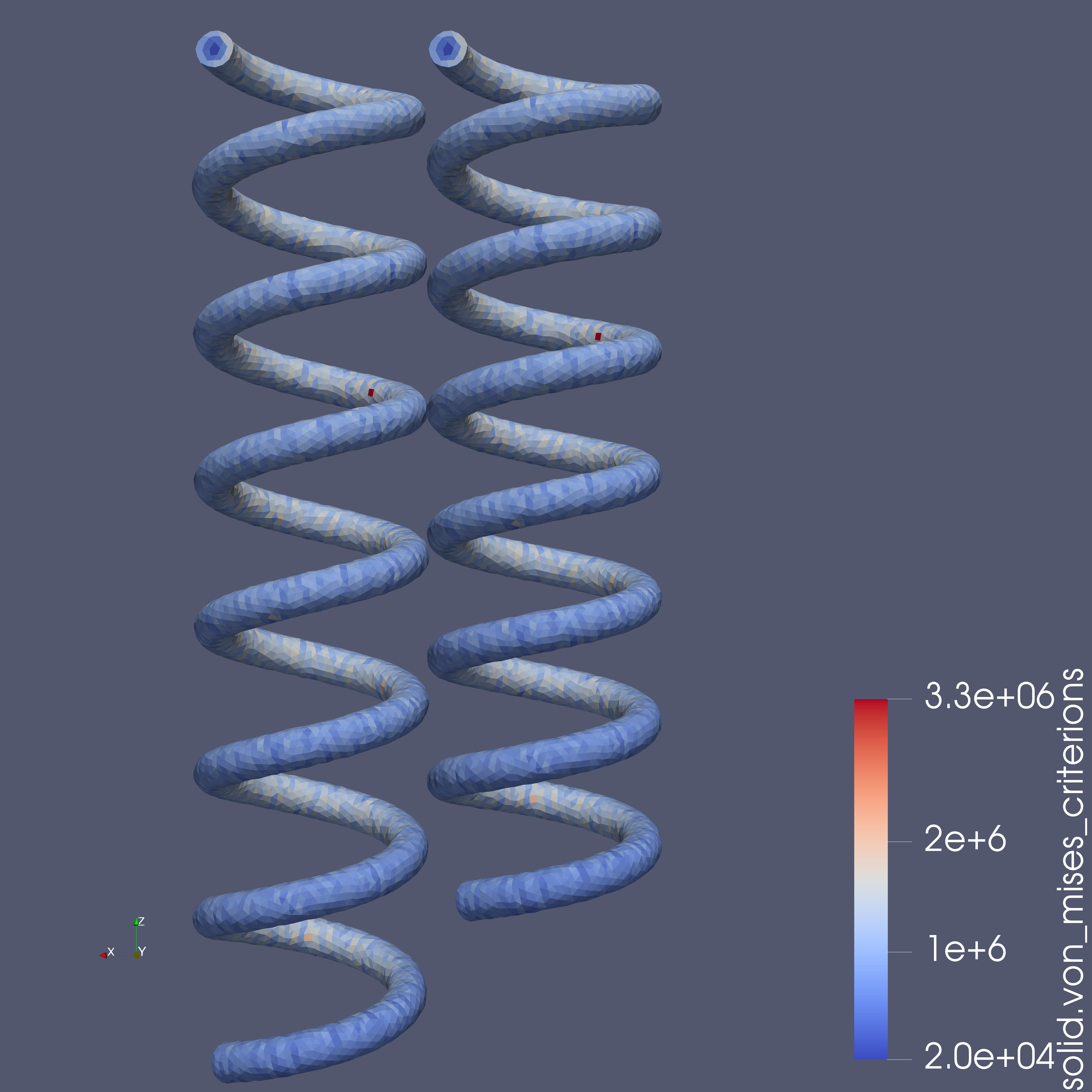
The fields of interest are the displacement, the von Mises yield criterion and the parallel process id (pid). The pid helps to see how the mesh was partitioned for parallel processing. In the 3D view below, when selecting the pid in the first dropdown list, each color corresponds to a subdomain assigned to and processed by a CPU core.
  "Parameters":
  {
    "dispImposed":
    {
      "value":"8e-3" // [m]
    },
    "gravity":
    {
      "value":"9.80665" // [m.s^{-2}]
    }
  },
"PostProcess":
{
"Exports":
{
"fields":["displacement","pressure","pid","von-mises-criterion"]
}
} .pdf
.pdf

